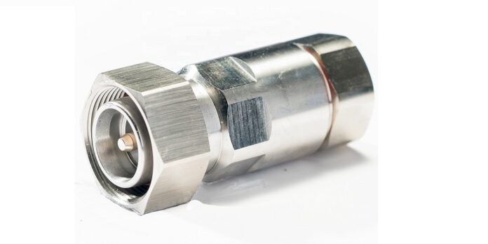
The 4.3-10 connector is a relatively new type of connector that has grown in popularity because of its exceptional features. RF connectors are crucial parts of modern communication systems. You’ll closely examine the 4.3 10 adapter specifications in this article.
Impedance
The standard impedance employed in most RF applications is 50 ohms, which is the impedance of the 4.3-10 connector. This feature guarantees that the connector is compatible with other system parts and that the signal is transmitted with the least loss.
Frequency Range
The highest frequency that a connector can handle depends on its frequency range. The 4.3-10 connector is perfect for high-speed applications like cellular base stations, small cell applications, and distributed antenna systems because it has a frequency range of DC to 6 GHz.
Voltage Standing Wave Ratio (VSWR)
A crucial specification that shows how much energy has reflected the source as a result of impedance mismatches is a connector’s VSWR. Low VSWR values for the 4.3-10 connector range from 1.15 to 3 GHz and 1.20 to 6 GHz. The signal loss is kept to a minimum, and the signal quality is maintained thanks to the low VSWR.
Passive Intermodulation (PIM)
For connectors used in high-density applications, PIM is an essential specification. When two or more signals are combined, interference called PIM results. Because of the 4.3-10 connector’s low PIM value of -166 dBc, the signal quality is guaranteed to be preserved, and system performance is unaffected.
Insertion Loss
The energy lost when a signal travels through a connector is measured as insertion loss. Insertion loss for the 4.3-10 connector is 0.10 dB up to 3 GHz and 0.15 dB up to 6 GHz. The signal is transmitted with little loss and is kept in good condition thanks to the low insertion loss.
Operating Voltage
The maximum voltage a connector can withstand without damage is the operating voltage. With an operating voltage of 500 V RMS, the 4.3-10 connector is suitable for high-power applications.
Dielectric Withstanding Voltage
The dielectric withstanding voltage is the highest voltage the connector’s insulating material can withstand before degrading. The 4.3-10 connector can be used in high-voltage applications due to its 2,500 V RMS dielectric withstanding voltage.
Connector Durability
A connector’s durability is determined by how many mating cycles it can withstand before breaking down. Five hundred mating cycles of durability for the 4.3-10 connector ensure that it can withstand repeated use without breaking.
Operating Temperature
The operating temperature range is the range of temperatures a connector can operate within without getting damaged. With an operating temperature range of -40°C to +85°C (-40°F to +185°F), the 4.3-10 connector can be used in a variety of settings.
Materials
The 4.3-10 connector is typically made of brass, which is silver or nickel-plated to improve its conductivity. The beryllium copper center contact has been gold-plated to increase conductivity. The connector’s dielectric material is PTFE or another high-performance dielectric material.
Conclusion
In conclusion, 4.3-10 has many advantages over other connector types. It is perfect for high-speed applications due to low VSWR, PIM, and insertion loss. Additionally, the connector is strong and can withstand repeated use without breaking. It is suitable for high-power and high-voltage applications due to its operating and dielectric withstanding voltage. In general, anyone looking for a dependable, high-performance connector that can satisfy the requirements of modern communication systems should strongly consider the 4.3-10 connector.


